Use the space
between the sheds.
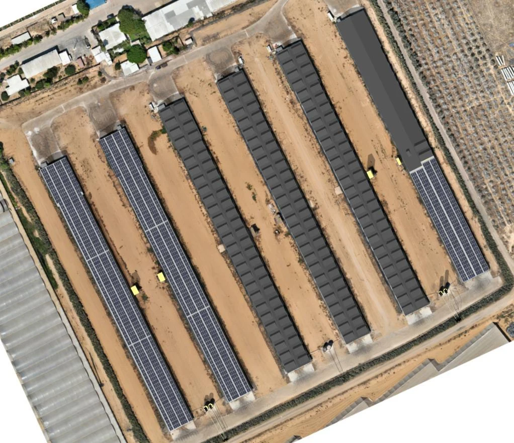
Two independent structures create additional solar area within the farm layout, without transferring their loads to the existing shed roofs.
 AMIOZ / EXECUTIVE BRIEFING
AMIOZ, ISRAEL · SOLAR EXPANSION
A proposal to add 757.76 kWp between the central poultry sheds, balancing new solar capacity with tractor access and protection of existing roof generation.
Msc. Joseph Abinun

THE EXECUTIVE PERSPECTIVE
Two independent structures create additional solar area within the farm layout, without transferring their loads to the existing shed roofs.
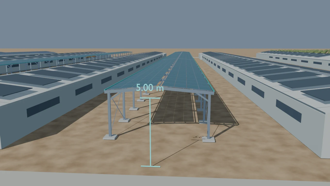
A five-metre total height limit, transverse tractor access and shade on neighbouring panels shape the concept from the start.
Progress to survey, structural feasibility and a coordinated PV layout before fixing capacity, cost or expected annual yield.
THE PROJECT IN 30 SECONDS
Start above G5, cross the new structures, then move closer to see their height, tractor access and winter shadows.
A visual explanation of the engineering concept. The opening landscape is illustrative; height, access and winter-shadow views follow the R2 design geometry.
MUSIC & ENGLISH SUBTITLES · CONCEPT R2THE SPATIAL STRATEGY
Two freestanding steel canopies sit in the G3–G4 and G4–G5 gaps. Low-pitch gable roofs keep the edges beside the existing roof panels relatively low.
CANOPY 01
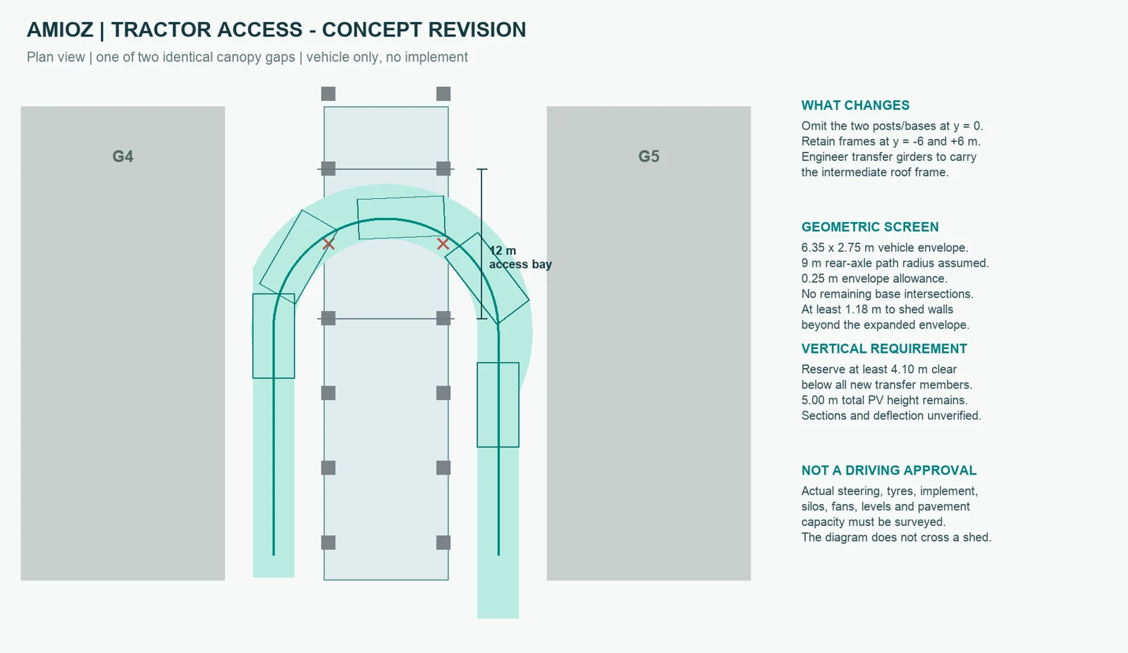
A separate crossing bay is reserved within this canopy. The route crosses from one side lane to the other.
G4 remains between the two canopies. The tractor crossings are separate movements through each canopy; the proposal does not create a route through a poultry shed.
AGRICULTURAL ACCESS
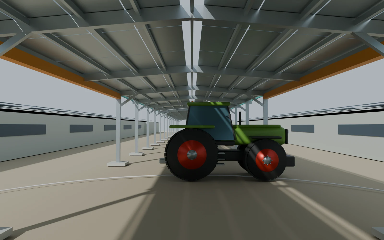
A 12 m bay replaces the typical 6 m frame spacing at the crossing. Intermediate columns are omitted; the supporting transfer members still need structural design.
Fendt 1050 Vario dimensional proxy, without an implement. Antennas, equipment, actual ground levels and structural deflection must be checked before approving access.
STRUCTURE & MOUNTING
Preliminary design basis for two 10 × 180 m canopies. The final panel model, steel sections and K2 attachment package remain to be selected and calculated.
Use a two-column, low-pitch portal arrangement with a nominal 6 m frame grid. Reserve a 12 m crossing bay through local transfer girders, with bracing and column protection kept outside the vehicle path. Steel grade, member sizes, connections and foundations require the project engineer’s design.
Develop a SolidRail or SingleRail interface to the steel purlins with K2. Confirm rail support spacing, fastener pull-out, module clamp zones and frame height. The rails do not replace the primary steel or bridge the tractor bay. K2 system reference ↗
MultiRail is a direct sheet-metal attachment option only if a compatible roof sheet is included and verified. An open purlin canopy needs a separately agreed connection. MultiRail scope ↗
5.00 − 5.00 × tan(5°) = 4.563 m at the eave plane. Above a 4.10 m soffit target, only 0.463 m remains for the module, rail, purlin, beam stack and allowances.
The 12 m transfer girder may control feasibility. Demonstrate member depth, connection geometry and deflection within this envelope before confirming tractor clearance.
Mechanical proxy: Trina Vertex N TSM-NEG19RC.20, 2382 × 1134 × 30 mm. The cited sheet covers 610–635 W, so it supports the mass and dimensions only. The project’s 640 W rating and 757.76 kWp remain planning assumptions until the exact module is selected. Trina mechanical reference ↗
| Item | One canopy | Both canopies | Basis |
|---|---|---|---|
| Module mass | 19.54 t | 39.07 t | 592 × 33 kg per canopy |
| Mounting budget allowance | 4.80 t | 9.59 t | 3 kg/m² × module area; estimating allowance, not a K2 bill of materials |
| Modules + mounting allowance | 24.33 t | 48.67 t | Excludes structural steel, roof sheet, cables, walkways and other loads |
| Heavier-module sensitivity | 23.68 t | 47.36 t | 40 kg per panel, modules only; illustrative scenario |
33 kg corresponds to about 12.22 kg/m² (0.120 kN/m²) over module area, or 0.106 kN/m² averaged over the 1800 m² canopy footprint. Average roof loads do not replace individual support reactions. Actual K2 mass must be calculated from rail lengths × kg/m plus clamps, brackets, splices and fasteners; catalogue examples range from 0.70 to 1.70 kg/m for the listed SolidRail profiles. K2 rail mass reference ↗
K2 publishes approximately 3.05 m clearance and a maximum 10.3 m span for the illustrated standard carport, below this project’s 4.10 m clearance target. Those published dimensions do not demonstrate the required 12 m transfer-bay configuration. A bespoke K2 proposal could be reviewed, but the catalogue product is not an approved substitute for the engineered frame. K2 carport dimensions ↗
Combine verified dead loads with local-code wind uplift and downward pressure for an open canopy, edge and corner effects, maintenance actions, temperature movements and applicable seismic actions. Check steel stability, deflection, connections, anchor tension, foundation uplift and soil bearing. Do not treat a module test-pressure rating as the canopy’s design resistance.
Specify corrosion protection for the actual poultry-farm exposure, including ammonia and cleaning chemicals. Confirm aluminium-to-steel interfaces, approved fasteners, bonding, drainage and module suitability above a vehicle route. Place expansion joints and bracing through an engineered scheme for the 180 m length. Panels with open joints are not a waterproof roof.
EXISTING GENERATION / WINTER SHADING
The 5 m height limit is only part of the picture. Existing roof and panel elevations strongly affect when additional shade reaches the neighbouring arrays.
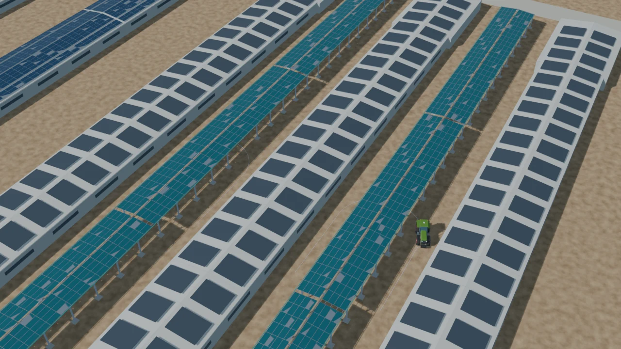
Rendered R2 geometry; the camera also moves slightly. This geometric study does not measure annual energy output.
First sampled afternoon intersection on 21 December, using assumed roof heights and five-minute calculation steps.
Shade begins earlier if the receiving panels are one metre lower than assumed. A level survey is a priority.
The screen tests 17,280 receiving-roof points. It does not calculate annual production or module-level electrical losses.
| Option | First afternoon hit | Sample area at 16:30 |
|---|---|---|
| 10 m width / 5° · working concept | 16:15 | 22.04% |
| 8 m width / 5° | 16:15 | 18.09% |
| 14 m width / 5° | 16:15 | 22.59% |
| 10 m width / 2° | 16:00 | 15.13% |
| 10 m width / 8° | 16:15 | 22.59% |
A narrower roof reduces this late-afternoon sampled shade, but would need a revised module layout and likely less capacity. A flatter roof raises the eaves within the same 5 m height limit and starts shading earlier in this screen. See the report for all assumptions.